
Description
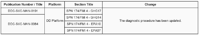
1. 06 09-16

Additions, Revisions, or Updates
DiagnosticLink users: Please update the troubleshooting guides in DiagnosticLink with this newest version. To update the tool troubleshooting guide, open DiagnosticLink and from the Help – Troubleshooting Guides menu, select the appropriate troubleshooting manual, then click Update.
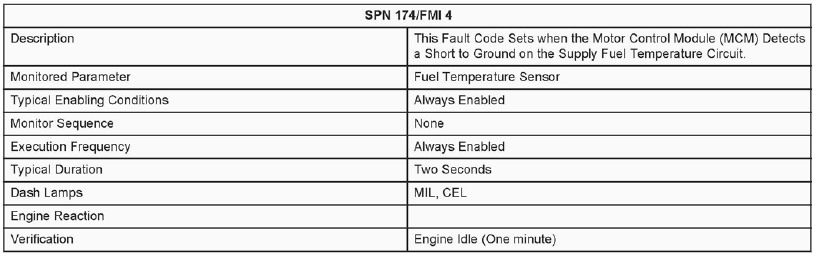
2. SPN 174/FMI 4 – GHG17
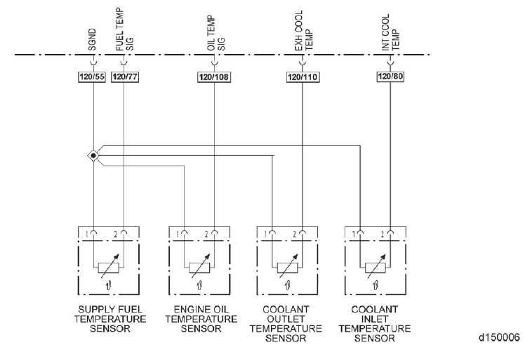
Supply Fuel Temperature Sensor Short Circuit to Ground
Table 1.
Check as follows:
1. Connect DiagnosticLink ®.
2. Disconnect and inspect the fuel temperature sensor electrical connector harness side. Is there any corrosion present?
a. Yes; replace the fuel temperature sensor and the electrical connector. Refer to section “Removal of the Supply
Fuel Temperature Sensor” and Technical Service letter 13 TS-16 (http://ddcsn-ddc.freightliner.com/cps/rde/
xbcr/ddcsn/13TS16.pdf) . Verify repair.
b. No; Go to step 3.
3. Are any of the pins or the connector damaged?
a. Yes; Go to step 4.
b. No; Go to step 5.
4. Inspect the fuel temperature sensor electrical connector components side. Are any of the pins or the connector
damaged?
a. Yes; replace the fuel temperature sensor and the electrical connector. Refer to section “Removal of the Supply
Fuel Temperature Sensor” and Technical Service letter 13 TS-16 (http://ddcsn-ddc .freightliner.com/cps/rde/
xbcr/ddcsn/13TS16.pdf) . Verify repair.
b. No; replace the fuel temperature sensor electrical connector. Refer to section “Removal of the Supply Fuel
Temperature Sensor”. Verify repair.
5. With the fuel temperature sensor disconnected, tum the ignition ON (Key ON, Engine OFF).
6. Is fault code SPN 175/FMI 4 still active?
a. Yes; Go to step 7.
b. No; replace the fuel temperature sensor. Refer to section “Removal of the Supply Fuel Temperature Sensor”. Verify repair.
7. Tum the ignition OFF.
8. Disconnect and inspect the MCM 120-pin electrical connector harness side. Is there corrosion present?
a. Yes; replace the MCM and the engine harness. Refer to section “Removal of the Motor Control Module” and
Refer to section “Removal of the Engine Wiring Harness” . Verify repair.
b. No; Go to step 9.
9. Are any of the pins or the connector damaged?
a. Yes; Go to step 10.
b. No; Go to step 11.
10. Inspect the MCM 120-pin electrical connector component side. Are any of the pins or the connector damaged?
a. Yes; replace the MCM and the electrical connector. Refer to section “Removal of the Motor Control Module”
and Refer to section “Removal of the Engine Wiring Harness”. Verify repair.
b. No; replace the engine harness. Refer to section “Removal of the Engine Wiring Harness”. Verify repair.
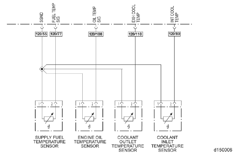
11 . Measure the resistance between pin 2 of the supply fuel temperature sensor electrical connector harness side and pin 77 of the MCM 120-pin electrical connector harness side. Is the resistance less than 10k ohms?
a. Yes; repair the circuit between pin 2 of the supply fuel temperature sensor electrical connector harness side and pin 77 of the MCM 120-pin electrical connector harness side.
b. No; replace the MCM. Refer to section “Removal of the Motor Control Module”. Verify repair.
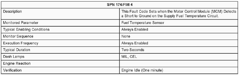
3. SPN 174/FMI 4 – GHG14
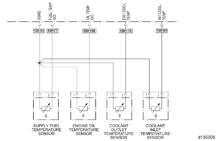
Supply Fuel Temperature Sensor Short Circuit to Ground
Table 2.
1. Connect DiagnosticLink ®.
2. Disconnect and inspect the fuel temperature sensor electrical connector harness side. Is there any corrosion present?
a. Yes; replace the fuel temperature sensor and the electrical connector. Refer to section “Removal of the Supply
Fuel Temperature Sensor – Two-Filter Fuel System” and Technical Service letter 13 TS-16 (http://ddcsn-ddc. freightliner.com/cps/rde/xbcr/ddcsn/13 TS16.pdf) . Verify repair.
b. No; Go to step 3.
3. Are any of the pins or the connector damaged?
a. Yes; Go to step 4.
b. No; Go to step 5.
4. Inspect the fuel temperature sensor electrical connector components side. Are any of the pins or the connector
damaged?
a. Yes; replace the fuel temperature sensor and the electrical connector. Refer to section “Removal of the Supply
Fuel Temperature Sensor – Two-Filter Fuel System” and Technical Service letter 13 TS-16 (http://ddcsn-
ddc .freightliner. com/cps/rde/xbcr/ddcsn/13TS 16.pdf) . Verify repair.
b. No; replace the fuel temperature sensor electrical connector. Refer to section “Removal of the Supply Fuel
Temperature Sensor – Two-Filter Fuel System”. Verify repair.
5. Tum the ignition ON (Key ON, Engine OFF).
6. Is fault code SPN 175/FMI 4 still active?
a. Yes; Go to step 7.
b. No; replace the fuel temperature sensor. Refer to section “Removal of the Supply Fuel Temperature Sensor –
Two-Filter Fuel System”. Verify repair.
7. Tum the ignition OFF.
8. Disconnect and inspect the MCM 120-pin electrical connector harness side. Is there corrosion present?
a. Yes; replace the MCM and the engine harness. Refer to section “Removal of the Motor Control Module”.
Verify repair.
b. No; Go to step 9.
9. Are any of the pins or the connector damaged?
a. Yes; Go to step 10.
b. No; Go to step 11.
10. Inspect the MCM 120-pin electrical connector component side. Are any of the pins or the connector damaged?
a. Yes; replace the MCM and the electrical connector. Refer to section “Removal of the Motor Control Module”.
Verify repair.
b. No; replace the engine harness.
11 . Measure the resistance between pin 2 of the supply fuel temperature sensor electrical connector harness side and pin 77 of the MCM 120-pin electrical connector harness side. Is the resistance less than 10k ohms?
a. Yes; repair the circuit between pin 2 of the supply fuel temperature sensor electrical connector harness side and pin 77 of the MCM 120-pin electrical connector harness side.
b. No; replace the MCM. Refer to section “Removal of the Motor Control Module”. Verify repair.
4. SPN 174/FMI 4 – EPA10
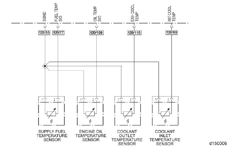
Supply Fuel Temperature Sensor Short Circuit to Ground
Table 3.

Check as follows:
1. Connect DiagnosticLink ®.
2. Disconnect and inspect the fuel temperature sensor electrical connector harness side. Is there any corrosion present?
a. Yes; replace the fuel temperature sensor and the electrical connector.
Refer to section “Removal of the Supply Fuel Temperature Sensor – Two-Filter Fuel System” for the two filter
system, and Technical Service letter 13 TS-16 (http://ddcsn-ddc .freightliner.com/cps/rde/xbcr/ddcsn/
13TS16.pdf) . Verify repair.
Refer to section “Removal of the Supply Fuel Temperature Sensor – Three-Filter Fuel System” for the three
filter system, and Technical Service letter 13 TS-16 (http://ddcsn-ddc.freightliner.com/cps/rde/xbcr/ddcsn/
13TS16.pdf) . Verify repair.
b. No; Go to step 3.
3. Are any of the pins or the connector damaged?
a. Yes; Go to step 4.
b. No; Go to step 5.
4. Inspect the fuel temperature sensor electrical connector components side. Are any of the pins or the connector
damaged?
a. Yes; replace the fuel temperature sensor and the electrical connector.
Refer to section “Removal of the Supply Fuel Temperature Sensor – Two-Filter Fuel System” for the two filter
system, and Technical Service letter 13 TS-16 (http://ddcsn-ddc .freightliner.com/cps/rde/xbcr/ddcsn/
13TS16.pdf) . Verify repair.
Refer to section “Removal of the Supply Fuel Temperature Sensor – Three-Filter Fuel System” for the three
filter system, and Technical Service letter 13 TS -16 (http://ddcsn-ddc.freightliner.com/cps/rde/xbcr/ddcsn/
13TS16.pdf) . Verify repair.
b. No; replace the fuel temperature sensor electrical connector. Refer to Technical Service Letter 13 TS-16 (http://
ddcsn-ddc .freightliner.com/cps/rde/xbcr/ddcsn/1 3TS16.pdf) . Verify repair.
5. Tum the ignition ON (Key ON, Engine OFF).
6. Is fault code SPN 175/FMI 4 still active?
a. Yes; Go to step 7.
b. No; replace the fuel temperature sensor. Refer to section “Removal of the Supply Fuel Temperature Sensor –
Two-Filter Fuel System”, or Refer to section “Removal of the Supply Fuel Temperature Sensor – Three-Filter
Fuel System” for the three filter system. Verify repair.
7. Tum the ignition OFF.
8. Disconnect and inspect the MCM 120-pin electrical connector harness side. Is there corrosion present?
a. Yes; replace the MCM and the engine harness. Refer to section “Removal of the Motor Control Module”.
Verify repair.
b. No; Go to step 9.
9. Are any of the pins or the connector damaged?
a. Yes; Go to step 10.
b. No; Go to step 11.
10. Inspect the MCM 120-pin electrical connector component side. Are any of the pins or the connector damaged?
a. Yes; replace the MCM and the electrical connector. Refer to section “Removal of the Motor Control Module”.
Verify repair.
b. No; replace the engine harness.
11 . Measure the resistance between pin 2 of the supply fuel temperature sensor electrical connector harness side and pin 77 of the MCM 120-pin electrical connector harness side. Is the resistance less than 10k ohms?
a. Yes; repair the circuit between pin 2 of the supply fuel temperature sensor electrical connector harness side and pin 77 of the MCM 120-pin electrical connector harness side.
b. No; replace the MCM. Refer to section “Removal of the Motor Control Module”. Verify repair.
5. SPN 174/FMI 4 – EPA07
Supply Fuel Temperature Sensor Short Circuit to Ground
Table 4.

Check as follows:
1. Connect DiagnosticLink ®.
2. Disconnect and inspect the fuel temperature sensor electrical connector harness side. Is there any corrosion present?
a. Yes; replace the fuel temperature sensor and the electrical connector. Refer to section “Removal of the Supply
Fuel Temperature Sensor – Three-Filter Fuel System” and Technical Service letter 13 TS-16 (http://ddcsn-ddc .freightliner. com/cps/rde/xbcr/ddcsn/13 TS16.pdf) . Verify repair.
b. No; Go to step 3.
3. Are any of the pins or the connector damaged?
a. Yes; Go to step 4.
b. No; Go to step 5.
4. Inspect the fuel temperature sensor electrical connector components side. Are any of the pins or the connector
damaged?
a. Yes; replace the fuel temperature sensor and the electrical connector. Refer to section “Removal of the Supply
Fuel Temperature Sensor – Three-Filter Fuel System” and Technical Service letter 13 TS-16 (http://ddcsn-
ddc .freightliner. com/cps/rde/xbcr/ddcsn/13TS16.pdf) . Verify repair.
b. No; replace the fuel temperature sensor electrical connector. Refer to Technical Service Letter 13 TS-16 (http://
ddcsn-ddc .freightliner.com/cps/rde/xbcr/ddcsn/1 3TS16.pdf) . Verify repair.
5. Tum the ignition ON (Key ON, Engine OFF).
6. Is fault code SPN 175/FMI 4 still active?
a. Yes; Go to step 7.
b. No; replace the fuel temperature sensor. Refer to section “Removal of the Supply Fuel Temperature Sensor –
Three-Filter Fuel System”. Verify repair.
7. Tum the ignition OFF.
8. Disconnect and inspect the MCM 120-pin electrical connector harness side. Is there corrosion present?
a. Yes; replace the MCM and the engine harness. Refer to section “Removal of the Motor Control Module”.
Verify repair.
b. No; Go to step 9.
9. Are any of the pins or the connector damaged?
a. Yes; Go to step 10.
b. No; Go to step 11.
10. Inspect the MCM 120-pin electrical connector component side. Are any of the pins or the connector damaged?
a. Yes; replace the MCM and the electrical connector. Refer to section “Removal of the Motor Control Module”.
Verify repair.
b. No; replace the engine harness.
11 . Measure the resistance between pin 2 of the supply fuel temperature sensor electrical connector harness side and pin 77 of the MCM 120-pin electrical connector harness side. Is the resistance less than 10k ohms?
a. Yes; repair the circuit between pin 2 of the supply fuel temperature sensor electrical connector harness side and pin 77 of the MCM 120-pin electrical connector harness side.
b. No; replace the MCM. Refer to section “Removal of the Motor Control Module”. Verify repair.


Reviews
There are no reviews yet.