
The N2 Electronic Unit Injector (EUI) is a lightweight, compact unit that injects diesel fuel directly into the combustion chamber. See Figure "N2 Electronic Unit Injector Cross-section" .
|
1. Spray Tip |
11. Injector Body |
|
2. Spring Cage |
12. Plunger |
|
3. Check Valve Cage |
13. Upper O-ring Grooves and Seals |
|
4. Spacer |
14. Fuel Outlet Openings |
|
5. Fuel Inlet Opening |
15. Injector Nut |
|
6. Fuel Supply Chamber |
16. Lower O-rings Grooves and Seals |
|
7. Poppet Control Valve |
17. Flat Disk Check Valve |
|
8. Solenoid |
18. Injector Needle Valve Spring |
|
9. Injector Follower |
19. Needle Valve |
|
10. Injector Follower Spring |
|
Figure 1. N2 Electronic Unit Injector Cross-section
The amount of fuel injected and the beginning of injection timing is determined by the ECM. The ECM sends a command pulse which activates the injector solenoid. The EUI performs four functions:Engine combustion is obtained by injecting, under pressure, a small quantity of accurately metered and finely atomized fuel oil into the cylinder. Metering and timing of the fuel is accomplished by the ECM which actuates the solenoid poppet valve to stop the free flow of fuel through the injector. When the solenoid poppet valve closes, fuel is trapped in the injector body and under the plunger. The continuous fuel flow through the injector prevents air pockets in the fuel system and cools those injector parts subjected to high combustion temperatures.
Note: Do not test new or reliabilt® remanufactured electronic unit injectors prior to installation in the engine. The Kent-Moore® POP stand should only be used as a diagnostic tool on fuel injectors that have been removed from an engine.
Fuel enters the injector through the two fuel inlet filter screens located around the injector body. See Figure "Fuel Injector Body" . Filter screens are used at the fuel inlet openings to prevent relatively coarse foreign material from entering the injector.

Figure 2. Fuel Injector Body
Note: Effective with September, 1988 production, Series 60 engine EUI nuts incorporate one upper seal ring groove and seal ring, instead of two. See Figure "N2 Electronic Unit Injector" .
Outlet openings, through which the excess fuel oil returns to the fuel return manifold and then back to the fuel tank, are located around the injector nut. See Figure "N2 Electronic Unit Injector" .
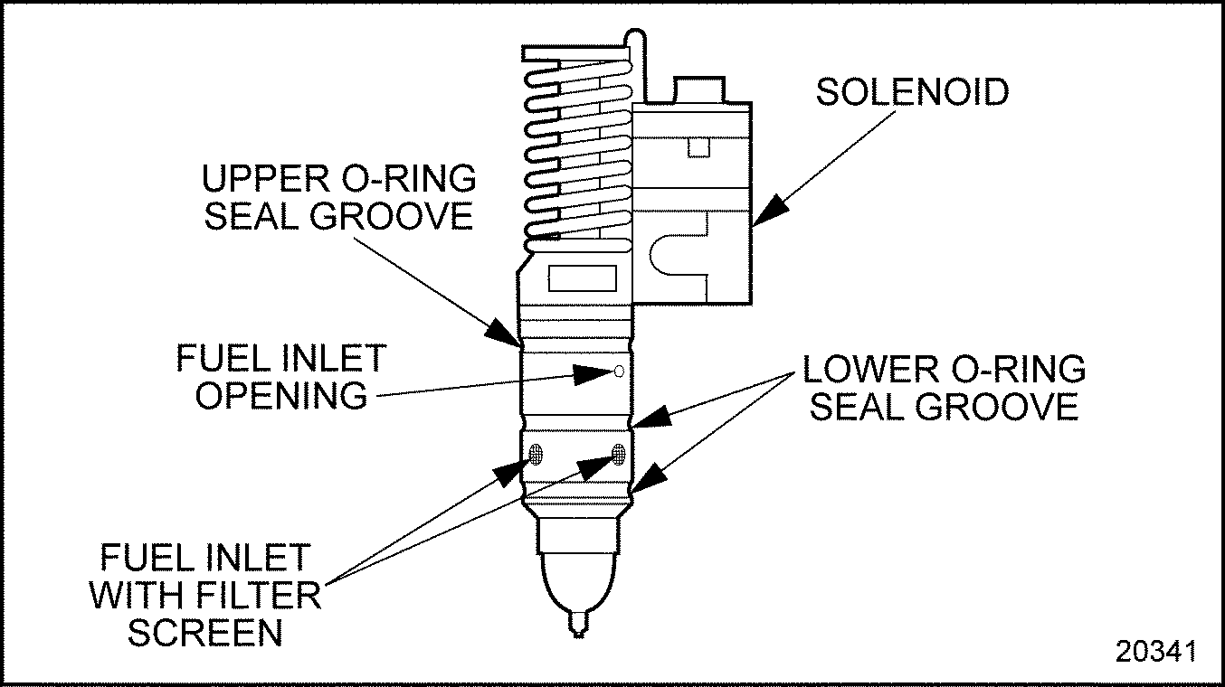
Figure 3. N2 Electronic Unit Injector
After entering the nut cavity, the fuel passes through a drilled passage into the poppet control valve and plunger area. See Figure "N2 Electronic Unit Injector Cross-section" .
The plunger operates up and down in the body bore of the injector. The motion of the injector rocker arm is transmitted to the plunger and follower that bears against the follower spring.
As the piston moves approximately two-thirds of the way up in the cylinder on the compression stroke, the injector cam lobe begins to lift causing the injector rocker arm to push down on the follower and the plunger. Just before injection begins, the ECM sends an electronic pulse which turns on the injector solenoid. The energized solenoid creates a magnetic force which pulls the armature up, closing the poppet valve and trapping fuel under the plunger and passages leading down to the needle valve. The fuel pressure increases as the plunger continues its downward stroke.
A flat disk check valve is built into the injector fuel passages between the plunger and the tip. This check valve normally has no effect on the injection process but will function to prevent cylinder gases from blowing back into the injector and fuel system if a particle of debris should become lodged between the needle and seat or the tip assembly fails.
This fuel pressure acts on the needle valve. When it creates a force high enough to overcome the valve spring force holding the needle on its seat, the needle valve moves up, allowing the high pressure fuel to spray into the combustion chamber. The high pressure of the fuel passing through the small holes in the tip creates a finely atomized spray for combustion within the cylinder.
After the pulse width time has passed, the ECM turns off the current to the injector solenoid. The de-energized solenoid allows a spring to open the poppet valve, permitting the trapped fuel to spill down, dropping the pressure within the injector. When the pressure is low enough the needle valve closes and ends injection.
The beginning of injection and metering of the fuel in relation to the crankshaft position are controlled by the ECM. Injection begins soon after the poppet valve is closed. The valve closing point information, known as the response time feedback, is returned to the ECM. This information is used to monitor and adjust injection timing, thus removing injector-to-injector variation influences on timing. The amount of fuel injected depends on the pulse width stored in the calibration which determines how long the poppet valve remains closed; the larger the pulse width the longer the valve is closed and the more fuel is injected.
When the injector rocker arm has completed its downward travel the injector follower spring returns it to the starting position. As the plunger moves up fuel enters the injector pumping cavity for another injection cycle. The constant circulation of fuel through the injector renews the fuel supply in the chamber and aids the cooling of the injector.
To determine if repair is possible or replacement is necessary perform the following procedure. See Figure "Flowchart for Repair or Replacement of N2 Electronic Unit Injector" .

Figure 4. Flowchart for Repair or Replacement of N2 Electronic Unit Injector
The following steps must be performed prior to removing an injector:
Note: The solenoid can be replaced without removing the injector. Refer to "2.3.4 Repair of N2 Electronic Unit Injector Solenoid and Seals" .
|
EYE INJURY |
|
To avoid injury from flying debris when using compressed air, wear adequate eye protection (face shield or safety goggles) and do not exceed 276 kPa (40 psi) air pressure. |
NOTICE: |
|
All the fuel must be removed from the cylinder head before removing an injector to prevent the fuel from entering the cylinder and causing hydrostatic lock or washdown. If the head is not thoroughly purged of fuel before an injector is removed, fuel remaining in the fuel manifold will drain into the cylinder filling the piston dome recess. It cannot drain from the dome and, if not removed, can cause hydrostatic lock and bend the connecting rod. |
Note: Front and rear rocker shaft assemblies look identical but are not interchangeable because of different bolt hole center distances. The outboard end of each rocker shaft assembly is marked with the DDC logo for identification. Care should be taken to identify and return assemblies to the proper location if both overhead assemblies are removed.
Note: Loosening the fuel line at the inlet fitting will allow fuel to flow faster. Carefully collect the drained fuel in an appropriate container.

Figure 5. Cylinder Head Fuel Fitting Locations
To remove the injector, complete the following steps:
NOTICE: |
|
Do not remove the screws from the injector. The wire terminals have keyhole slots to fit over the screw head. Turning the screws too far will damage the threads in the injector solenoid housing. |
NOTICE: |
|
Extreme care should be used when handling an EUI to avoid costly damage by dropping or otherwise mishandling the EUI. |
Note: When replacing an EUI, always replace the injector O-rings.
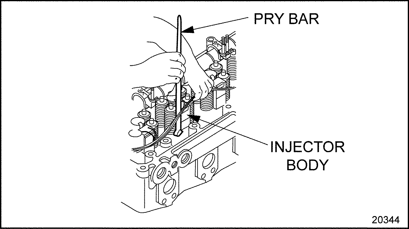
Figure 6. Removing N2 Electronic Unit Injector
NOTICE: |
|
Avoid wire brushing the spray holes to prevent damage. |
On a Series 60 engine EUI, only the injector solenoid and seal rings are serviceable. The injector must not be disassembled.
To clean and inspect the injector, complete the following steps:
Note: The injector can be tested either on or off of the engine.
|
EYE INJURY |
|
To avoid injury from flying debris when using compressed air, wear adequate eye protection (face shield or safety goggles) and do not exceed 276 kPa (40 psi) air pressure. |
Note: Do not test new or reliabilt® remanufactured electronic unit injectors prior to installation in the engine. The Kent-Moore® POP stand should only be used as a diagnostic tool on fuel injectors that have been removed from an engine.
Perform the following steps for solenoid replacement:

|
1. Spacer Seals |
4. Screw |
|
2. Solenoid |
5. Follower Retainer |
|
3. Load Plate |
6. Spacer |
Figure 7. Electronic Unit Injector Solenoid Assembly
NOTICE: |
|
The spacer is a matched component with the armature and must remain with its respective injector. |
NOTICE: |
|
The load plate on each DDEC III injector is unique and must remain with the injector. The DDEC III load plate carries the injector part number, the injector serial number in bar code format, and the injector calibration code number. |

Figure 8. N2 Electronic Unit Injector Solenoid Torque Sequence
Perform the following steps:
|
EYE INJURY |
|
To avoid injury from flying debris when using compressed air, wear adequate eye protection (face shield or safety goggles) and do not exceed 276 kPa (40 psi) air pressure. |
NOTICE: |
|
Leftover fuel must be removed from the injector bore before injector installation. If fuel is trapped between the top of the injector hole tube and the lower injector O-ring seal, it may seep down to the injector hole tube seal ring, causing swelling and possible seal leakage. |
Note: If the engine is equipped with an auxiliary injector tube seal, replace it with a new seal when the injector is removed.
NOTICE: |
|
Do not use a metal dowel as this may damage the seal. |
NOTICE: |
|
Injector seals are considered one-use items and cannot be reused. Any time an injector is removed, all three injector nut O-ring seals must be replaced with new seals. Failure to replace seals can result in seal leakage. |
Note: The injector tube bore should be cleaned and inspected for damage before installation of the electronic unit injector. Refer to "2.4.4 Cleaning of N2 Injector Tube" .
NOTICE: |
|
The hemispherical portion of the hold-down clamp washers must be installed facing the clamp (pointing down) in order to prevent damage to the washers. See Figure "N2 Electronic Unit Injector and Related Parts" . |

|
1. Injector Hold-down clamp |
5. Auxiliary Injector Seal |
|
2. Electronic Unit Injector |
6. Injector O-rings |
|
3. Injector Tube O-ring |
7. Hold-down Clamp Washer |
|
4. Injector Tube |
8. Hold-down Clamp Bolt |
Figure 9. N2 Electronic Unit Injector and Related Parts

Figure 10. Hold-down Clamp Washer Installation

Figure 11. N2 Electronic Unit Injector Terminal Installation
Note: Front and rear rocker shaft assemblies look identical but are not interchangeable due to different bolt-hole center distances. The outboard end of each rocker shaft assembly is marked with the DDC logo for identification. Care should be taken to identify and return assemblies to the proper location if both overhead assemblies were removed.
| Series 60 Service Manual - 6SE483 |
| Generated on 10-13-2008 |